
TCP/IP Model: The Data Link Layer: Error Detection and Correction
To properly learn something, we have to start at the beginning. We will be learning one concept at a time, process it, and move to the next.
The goal is consistent learning and absorbing information while feeling engaged and not overwhelmed.
I have divided the data link layer articles in five parts.
- Introduction to Data link layer
- Error Detection and Correction in Data link layer
- Flow and Error Control in Data link layer
- Protocols used in Data link layer
- Switches in Data link layer
Goal of this article
I will be explaining the error detection and correction in the data link layer of the TCP/IP Five-layer network model.
Errors in Data Link Layer
It is essential to know what types of errors may occur while transmission of data in the data link layer.
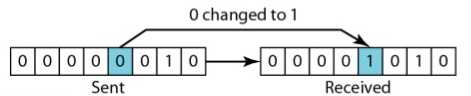
Single Bit Error
- In a frame, there is only one bit, anywhere though, which is corrupt.
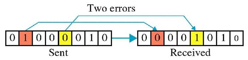
Multiple Bit Error
- Frame is received with more than one bit in a corrupted state.
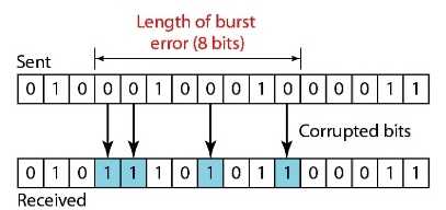
Burst Error
- Frame contains more than one consecutive bits corrupted.
Error Detection
-
Errors in the received frames are detected utilizing Parity Check and Cyclic Redundancy Check (CRC).
-
In both cases, few extra bits are sent along with actual data to confirm that bits received at the other end are the same as they were sent. If the counter-check at the receiver’s end fails, the bits are considered corrupted.
Parity Check
-
One extra bit is sent along with the original bits to make the number of 1s either even in case of even parity, or odd in case of odd parity.
-
The receiver simply counts the number of 1s in a frame.
-
If the count of 1s is even and even parity is used, the frame is considered to be not-corrupted and is accepted.
-
If the count of 1s is odd and odd parity is used, the frame is still not corrupted.
-
For example, if even parity is used and the number of 1s is even then one bit with the value 0 is added. This way number of 1s remains even. If the number of 1s is odd, to make it even a bit with value 1 is added.
Cyclic Redundancy Check (CRC)
-
This technique involves binary division of the data bits being sent.
-
The divisor is generated using polynomials.
-
The sender performs a division operation on the bits being sent and calculates the remainder.
-
The sender adds the remainder at the end of the actual bits.
-
Actual Data Bits + Remainder = Codeword -
The receiver performs division operations on codewords using the same CRC divisor.
-
If the remainder contains all zeros the data bits are accepted, otherwise it is considered as there some data corruption occurred in transit.
Error Correction
- Error correction can be done in two ways.
Backward Error Correction
-
When the receiver detects an error in the data received, it requests back the sender to retransmit the data unit.
-
Backward error correction is simple and can only be efficiently used where retransmitting is not expensive. For example, fiber optics.
Forward Error Correction
-
When the receiver detects some error in the data received, it executes an error-correcting code, which helps it to auto-recover and to correct some kinds of errors.
-
Forward Error Correction is used in the case of wireless transmission because retransmitting may cost too much.
-
To correct the error in the data frame, the receiver must know exactly which bit in the frame is corrupted. To locate the bit in error, redundant bits are used as parity bits for error detection.
Did you find this post useful?
I would be grateful if you let me know by commenting below. Means a lot to me!
Sign up to get updates when I write something new. No spam ever.
Comments